I play a lot of Elite: Dangerous. And while I use a reasonably nice HOTAS, I’ve long wanted a flight panel: a bank of toggle switches with LED indicators that would act as a USB joystick. I can only find one company selling such a thing, and their solution leaves exposed wiring. (a no-no when you live with cats) Also, their website looks like it is from the 90s and just feels kind of sketchy. (Seriously, guys, if you happen to read this, your website does not inspire confidence)
And, anyway, I’ve been looking for an excuse to learn some basic electronics for a long time. So, I built my own! Several other people have built similar things, but I decided to jump in head-first and not follow any guides, in hopes of learning about electronics and wiring along the way.
Acquiring Gear
First up, a parts list:- Wire! Stranded, 22 AWG wire is perfect for general hobbyist electronics work.
- An Arduino board, and an accompanying sensor shield. (But see my lessons learned section)
- 3-pin dupont connector housings combined with the sensor shield make it possible to wire each switch in a modular way.
- Female dupont connector pins or else the housings are useless.
- Some LEDs, and accompanying LED holders.
- Toggle switches, the satisfying clicky heart of the project.
- Resistors.
- A crimping tool.
- A wire stripper.
- A soldering iron, and several accompanying accessories.
- Smallish needle-nosed pliers.
- A drill. (a Unibit came in particularly handy)
- A router. (In future iterations, I’ll try to get away without one of these)
- A screwdriver.
- A 3D Printer (but see lessons learned!)
- Some nuts and bolts for binding everything together.
- A breadboard, with jumper wires and these really useful jumper/alligator clip wires.
Getting Started
void setup() {If this works as expected, then flipping the toggle switch should light up both the breadboard LED and the on-board LED (marked ‘L’ on the Arduino board). The logic is inverted (we write HIGH when we read LOW) because I’m using INPUT_PULLUP, which reverses the usual logic of the input pin. (This lets me wire the LED without worrying about how much current the input pin can sink. I’m probably being overly cautious here, actually.)
pinMode(2, INPUT_PULLUP);
pinMode(13, OUTPUT); // this is the Arduino’s on-board LED.
}
void loop() {
int state = digitalRead(2);
if (state == HIGH) digitalWrite(13, LOW);
else digitalWrite(13, HIGH);
}
Building the thing
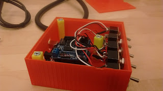
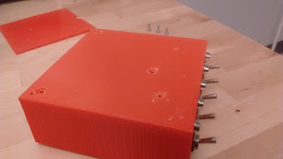
Now that I had a proof of concept, I moved on to building things in earnest. First, I needed a box to store it all in. I had trouble finding an appropriately-sized box (again, see “lessons learned”), so I decided to 3D Print one! I have access to a shared Ultimaker2 3D printer. So I designed and printed a box. I really don’t recommend using this design. This was my first attempt ever at 3D printing. The print took about 13 hours, and the resulting box had a bunch of problems, despite my attempt to make careful measurements. I had to drill out the holes for the switches more, and had to hack up the back pretty badly to get the USB port out. I also neglected to put mounting posts in for the lid, (I printed some later, but it was a huge pain) or holes to mount the arduino board on. (The odd bumps on the inside and the plastic bar were meant to be a little physical barrier to hold the board in place, but they printed out way too low to actually do anything.)So anyway, now I have a box. (the project quickly got nicknamed The Orange Box, naturally) Next, I created five of these, with varying LED colors:
- Strip the end of your wire.
- Twist the exposed wire strands together. (this is often a good idea when working with stranded wire)
- Lay the wire onto the ‘open’ part of the dupont pin, and push it in a bit. Ideally you want the bottom of the pin to be flush against your wire casing.
- Fold the metal flanges on the pin around the wire with needle-nosed pliers, so that it’s semi-closed.
- Crimp those flanges down with a crimp tool. Be careful not to crimp the ’top’ half of the pin, where you don’t have wire. You’ll need that to mate the pin with the headers on the board.
- Using the pliers again, squeeze the metal that was flattened by the crimp tool into a rounder shape.
- Insert the pin into the casing. (For this project, I hade to make sure the voltage line was in the middle, to match the pinout on the shield) There is a correct orientation but it’s a bit hard to describe. The pin should click into place and not come back out easily.
It takes a little practice to get the hang of it, but not having any connections soldered directly onto the Arduino makes it a lot more reusable!
Once I had all 5 of these, I mounted them in the box and wired them onto the sensor shield (which was connected to the arduino board. It just plugs right in on top!) With the 3-pin dupont widgets, this was super easy:
Programming the Thing
I wrote a simple library to interface with the Joystick firmware, and a sketch tailored to how I have my inputs setup and what I want them to do. The sketch interprets the toggle switches as momentary inputs; that is, it sends a short button-press event every time you toggle the switch, as opposed to “holding down” the button the entire time the switch is on. This design makes it work well with most of Elite: Dangerous’ controls.
In a future iteration I hope to make this all a bit more generalized and include a lot more functionality in the Joystick library. But for now, this works really well!
The Finishing Touches
After putting these in place, I briefly lamented not printing counter-sunk screw holes into the box, but then I realized ABS plastic was soft enough that I didn’t need them. All I had to do was tighten the screws a bit more, and:
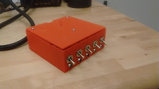
And finally, with everything screwed in place, the finished product:
Lessons Learned
- 3D printing the project box sounded super cool, but I wouldn’t do it again. It took too long, the resulting plastic is a bit weak for the job, and getting the hole placement just right was a pain. (and 3D printed parts don’t take especially well to drilling) For my next iteration of this box I’ve purchased a pre-made project box.
- If I were to 3D print again: remember to put screw-holes and posts in!
Mounting the LEDs was a bit of a problem, since the LED holders assume you’re wiring them in place. I couldn’t use their intended mounting setup, and had to just hot-glue them into place instead. This happened because the LED holders were back-ordered, and didn’t arrive until late in the project. - Soldering is fun, but moderately permanent. For future projects I’d rather invest in connectors that are slightly easier to disconnect. I bought a bunch of these in the hopes that the female connectors can mount to switch/button terminal posts. (early tests suggest they will work well)
- The Arduino Uno R3 + sensor shield is nice, but the total package is a bit big. I later discovered the Yourduino Robored, which has the same 3-row pinout as the sensor shield, but in a much smaller (and cheaper) package. I ordered a couple of these and intend to use them in future projects. One downside: they ship from Hong Kong and take a while to arrive.
- In the quiet of night (when I often play Elite) these toggle switches are loud enough to wake up and scare my housemate! I bought a bunch of rocker switches with LEDs already integrated for future use.


